产品详细
 首页
> 产品中心
> AP300 电源频响分析仪
> 产品详细
AP300 在电源行业的应用
- 产品详细
- 视频
-
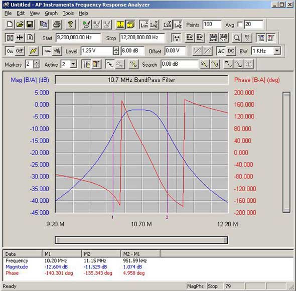
Graph of the Frequency Response of a 10.7 MHz Bandpass Filter
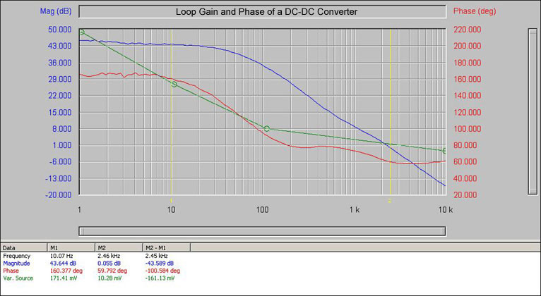
Graph of the Open Loop Gain and Phase of a DC-DC Converter Also Showing the Variable Source (green trace) in Use
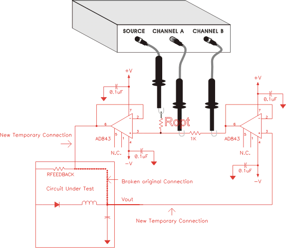
测试接线图
1. DC Coupled, Buffer Amplifier Method
Unless the feedback loop under test has a buffer stage with high input impedance and low output impedance it may be necessary to temporarily add such a stage to maintain the existing feedback loop characteristics and make a valid measurement. The diagram below shows the placement of such a temporary buffer and the network analyzer connections for a feedback loop frequency response measurement. The buffer circuit below, with the 35 MHz bandwidth op-amps, adds approximately 3 degrees of phase shift at 1 MHz to the measurement. Lower speed op-amps can be used for lower frequencies, if desired. The circuit shown assumes Zout @ Vout is much lower than Rfeedback over the frequencies of interest. If this is not the case then to obtain the actual loop gain response it may be necessary to terminate the Vout node with an impedance equivalent to Rfeedback and to add a series impedance to Rfeedback equal to Zout.
Buffer Circuit For DC Coupled Feedback Loop Measurements
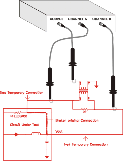
2. AC Coupled, Transformer Method
The secondary of a transformer is used in this technique to develop a drive voltage across a small resistor, typically 10 to 50 Ohms. This resistor is typically placed in series with the loop's feedback resistor as shown in the diagram below. The transformer's frequency response does not have to be flat over the measurement range but does need to provide an adequate drive level over the measurement range to ensure a good signal to noise ratio.
Configuration For Transformer Coupled Feedback Loop Measurements:
阻抗测试的基本设置:
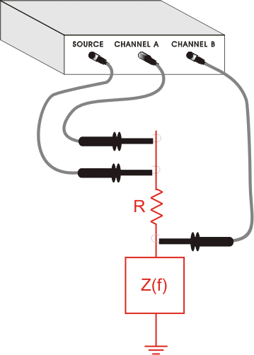
Complex Impedance Measurement Calculations:
Let the transfer function measured by the analyzer be H(f), the unknown complex impedance, Z(f)= x + j•y, is then given by: Z(f) = R•H(f)/(1-H(f)). This result is derived using the generalized voltage divider formula with the substitution of VB = H•VA.
-


